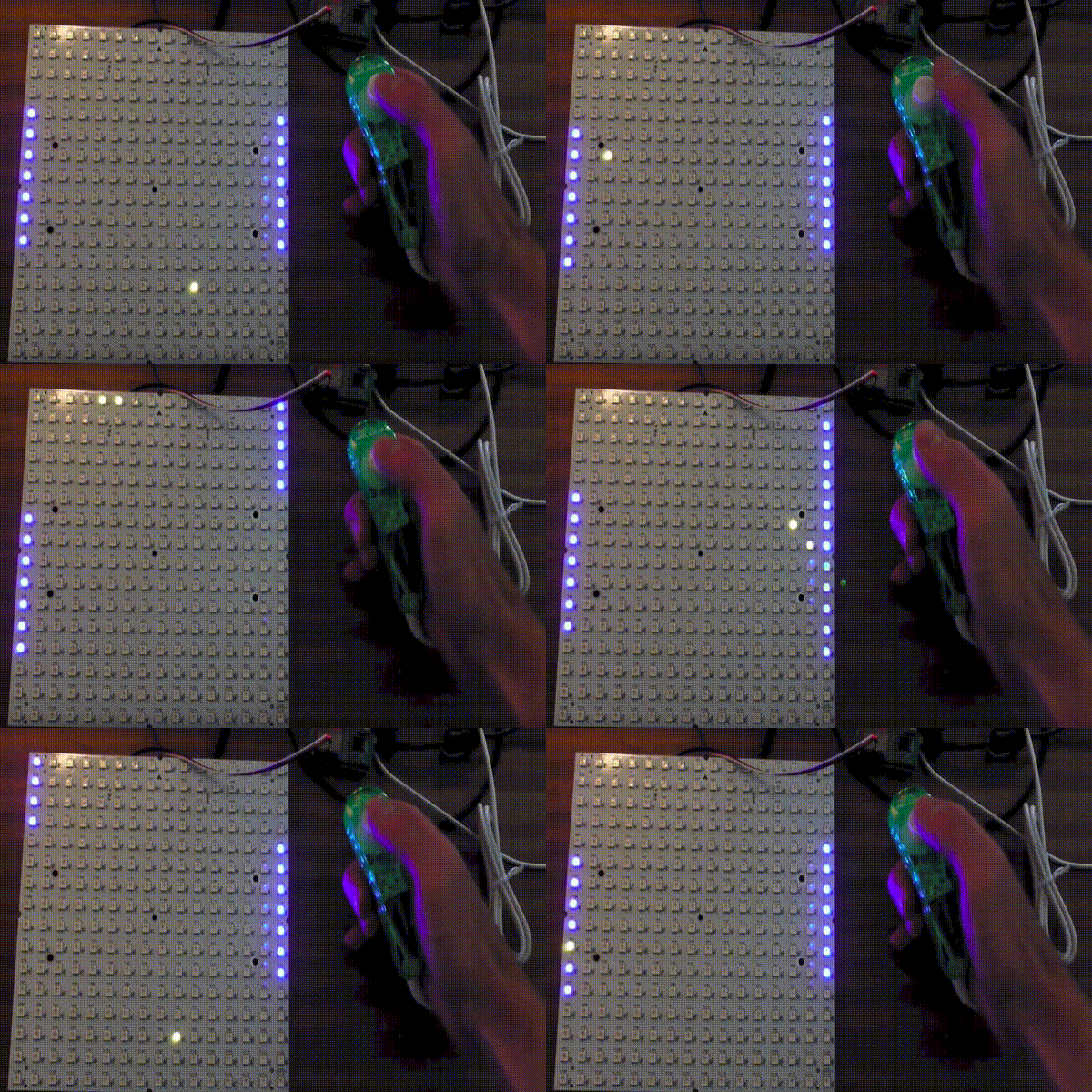
Espruino and the Wii Nunchuck
Espruino project demonstrates the Wii Nunchuck and the RGB123 LED Matrix
Back in 2013 the Espruino project demonstrated building a simple pong system using an RGB123 LED Matrix and a Wii Nunchuck

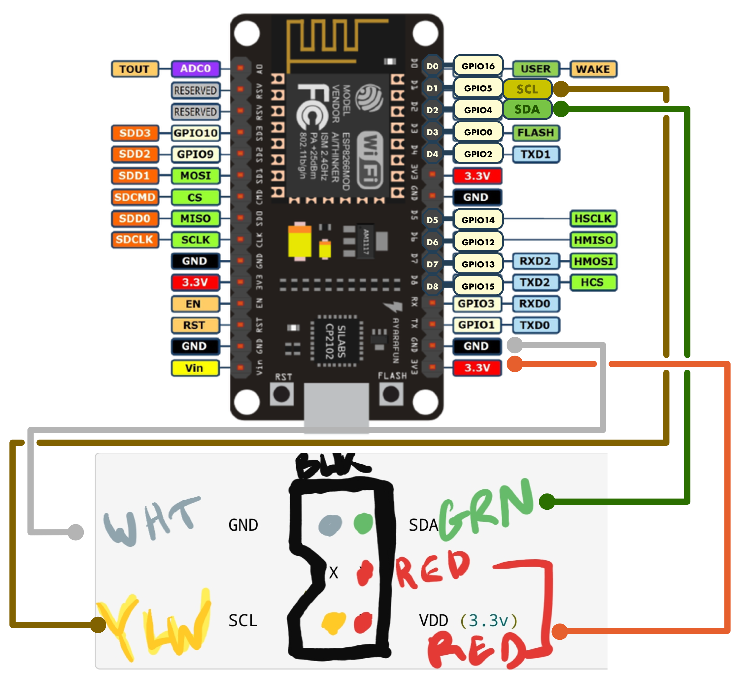
Wii Nunchuck Pinout
- The Wii Nunchuck is an I2C (synchronous serial computer bus) device.
- SDA and SCL need wiring up to the corresponding I2C pins (of the same I2C port) on the NodeMCU.
- According to variants/nodemcu/pins_arduino.h the default SDA/SCL pins on the NodeMCU are:
- SDA (data) = GPIO4 (D2)
- SCL (clock) = GPIO5 (D1)
| Nunchuck | Descr | Espruino | esp8266-01 | NodeMCU |
| White | Gnd | Gnd | Gnd | Gnd |
| Red | 3V3 | Vdd | Vdd | Vdd |
| Yellow | SCL | B6 | D0 | GPIO5 (D1) |
| Green | SDA | B7 | D2 | GPIO4 (D2) |
With Espruino and the NodeMCU, the “D” pin is the GPIO number, not the D-pin number.

The example provided by the Espruino project has the code as:
I2C1.setup({scl:D1,sda:D2});
var wii = require("wii_nunchuck").connect(I2C1);
console.log(JSON.stringify(wii.read()));
However, a forum post suggests that we will need to configure the ports and set the CPU frequency
var ESP8266 = require('ESP8266');
ESP8266.setCPUFreq(80);
pinMode(D1, 'opendrain'); // scl
pinMode(D2, 'opendrain'); // sda
I2C1.setup({scl:D1,sda:D2});