I am using the same NodeMCU board to test the DHT11 sensor as well.
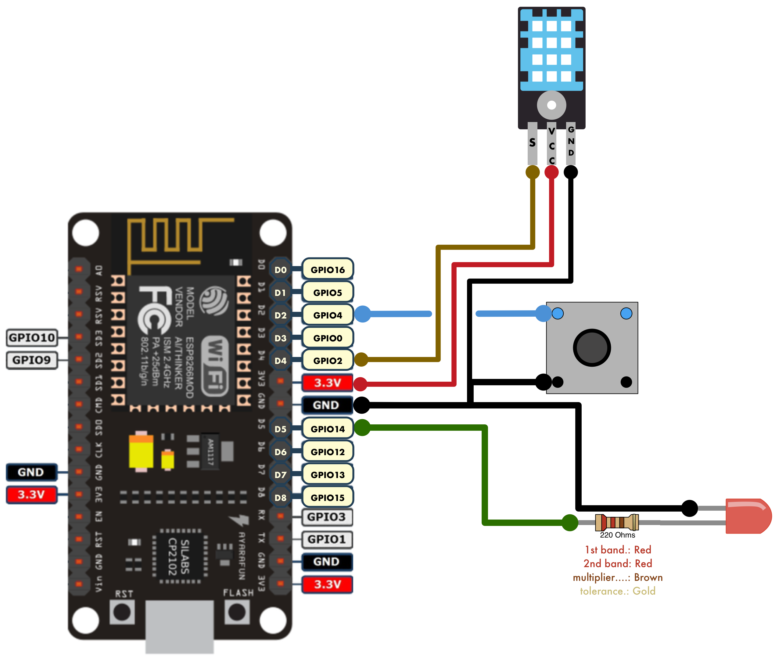
The button, DHT11, and LED each have a data pin.
The ground is common amongst all electronic pieces.
Control the LED
The short wire of the LED is the negative connection.
The connectors of the LED are important, ensure that the short wire is connected to ground.
The resistor ensures that the LED does not get overloaded.
The LED connects to NodeMCU data pin #5 (D5) which is GPIO Pin ID #14.
frommachineimportPinled=Pin(14,Pin.OUT)# pin value 1 = LED on
# pin value 0 = LED off
## turn LED off
led.value(0)## turn LED on
led.value(1)ledStatus="off"if (led.value()==1):ledStatus="on"print("LED Value: "+ledStatus)
Read the status of the Button
When the button is up (not depressed) the value is 1.
The LED connects to NodeMCU data pin #2 (D2) which is GPIO Pin ID #4.
Use the button to control the LED and display the current temperature
Print the temperature to stdout on the console.
When the button is pressed down, light the light up.
When the button is up, turn off the light.
The temperature can only be polled every 2 seconds so build a 2 second sleep in to the code. Ultimately this method would fail outside of a test as the light could be left on after the button was depressed.
importdhtfrommachineimportPinfromtimeimportsleepled=Pin(14,Pin.OUT)button=Pin(4,Pin.IN,Pin.PULL_UP)d=dht.DHT11(Pin(2))whileTrue:ifnotbutton.value():led.value(1)d.measure()c=d.temperature()h=d.humidity()f=(c*1.8+32)print("Temp is "+str(c)+"C ("+str(f)+"F) and RH is "+str(h))sleep(2)else:led.value(0)